
Tuesday, January 25, 2011
Advertising: 1960
Don't remember where I found this, so can't credit anyone (sorry), but it's interesting in that it dates from September 1960, and my vehicle six weeks earlier. Click on the picture any you'll have a larger version, which may be readable.


Monday, January 24, 2011
Front Springs
Final piece of the front assembly is now dismantled, and essentially if the weather was warmer then it would be on to cleaning and painting and reassembly on the new chassis. However, there are still a few small things to work out before then, in any case.
Here's a view of the front springs, and their shackle plates and bolts, with the new U-bolts and things in the box at top, and the new bushings at the bottom.

Here's the new mystery. The replacement bushings I purchased are not the same diameter as those in the springs. The new ones are 3.05 cm in diameter, which I understand is correct, while those in the springs are along the lines of 3.5 cm. Hmm, something else to solve.

Here's a view of the front springs, and their shackle plates and bolts, with the new U-bolts and things in the box at top, and the new bushings at the bottom.

Here's the new mystery. The replacement bushings I purchased are not the same diameter as those in the springs. The new ones are 3.05 cm in diameter, which I understand is correct, while those in the springs are along the lines of 3.5 cm. Hmm, something else to solve.

Saturday, January 22, 2011
Front Axle and Differential; Spring Dowels
Today, the final disassembly of the front axle components. U-bolts off (had to cut one with the angle grinder), axle removed, and differential taken out of the axle.
Here, bottom and top view of the axle, after a little light cleaning, along with the spring bottom plates (one being used for support).


And another view, with the differential removed, and the axle upended to drain out the few drops of remaining oil. When removing the differential, there was a forgotten pocket of oil in the casing which happily poured out onto the floor. Now the whole house smells vaguely Land-Rovery from the subtle sulpherous odour of EP90 - which isn't necessarily a bad thing. : )

Now the bad news: note the broken teeth on the differential wheels. Whatever caused the halfshaft to break apparently also caused damage elsewhere. This probably means sourcing a replacement differential, as I do not have the tools to correctly disassemble and reassemble this. In spite of this damage, the differential turned very easily by hand and without any noticeable indication of a problem.

Removing the axle casing revealed the dowels for the front springs. I don't know if these are both original; it may be necessary to order replacements. Why?

This is why. The head may be the right size, but clearly the threaded part on this one is not, extending a good two inches below the spring! (The other appears to be a correct length.) And while both heads are identical, they are both somewhat smaller than the holes in the axle supports that sit over the dowels. I'll have to see what the head sizes are on the originals, and take it from there.

Here, bottom and top view of the axle, after a little light cleaning, along with the spring bottom plates (one being used for support).


And another view, with the differential removed, and the axle upended to drain out the few drops of remaining oil. When removing the differential, there was a forgotten pocket of oil in the casing which happily poured out onto the floor. Now the whole house smells vaguely Land-Rovery from the subtle sulpherous odour of EP90 - which isn't necessarily a bad thing. : )


Removing the axle casing revealed the dowels for the front springs. I don't know if these are both original; it may be necessary to order replacements. Why?

This is why. The head may be the right size, but clearly the threaded part on this one is not, extending a good two inches below the spring! (The other appears to be a correct length.) And while both heads are identical, they are both somewhat smaller than the holes in the axle supports that sit over the dowels. I'll have to see what the head sizes are on the originals, and take it from there.

Friday, January 21, 2011
Prop Shaft Battle; Production Line
Oil seals for the front axle arrived here just 48 hours after placing the order with 3 Brothers Classic Rovers - which is typical of their truly excellent service.
Getting the proshaft bolts off proved to be a struggle, but they were eventually removed. They were all seized, and the awkward spaces around them makes getting tools in there difficult. Even the special prop shaft tool I had purchased didn't help, as it was blocked slightly by the yolks. On top of that, the prop shaft wanted to turn a little, making trying to turn the nuts frustrating, even with the rear wheels on the ground (in 4wd). After struggling with every approach I could think of, I ended up searching on the Rover forums at the options others have tried. I settled on 1: used a trusty 24" pipe wrench to immobilize the prop shaft; and 2: drilled a large hole in the side of the nuts, and then split them with a cold chisel. An easy process, it turned out, not taking too much effort or time. Of the four nuts nearest the front axle, one nut was already loose, two were drilled and spilt, and the last surrendered after being drilled only. The nuts themselves were very soft, and had rounded off immediately; don't think they were original. This thought was reinforced by the discovery that the four bolts were inappropriate for the prop shaft.
The four bolts on the right are those from the prop shaft at the front axle. The bolt at left is from the end at the gear box, and is the correct type (at least it has a shank, if not).

Prop shaft hangs its head in defeat. : )

A view of the front axle 'production line'. Everything here is just waiting for cleaning and/or paint, and then is ready to be then be reassembled (once the axle itself is off, cleaned and inspected). All the new bearing races, etc., are in place (except one bearing, which I damaged today while installing. Argh!) Lower left: Swivel assemblies; On the right: windshield under wraps (at top), and then the halfshafts, hubs and then brake backplate parts. Steering arms are just visible. The white cover is protecting the new chassis.

Getting the proshaft bolts off proved to be a struggle, but they were eventually removed. They were all seized, and the awkward spaces around them makes getting tools in there difficult. Even the special prop shaft tool I had purchased didn't help, as it was blocked slightly by the yolks. On top of that, the prop shaft wanted to turn a little, making trying to turn the nuts frustrating, even with the rear wheels on the ground (in 4wd). After struggling with every approach I could think of, I ended up searching on the Rover forums at the options others have tried. I settled on 1: used a trusty 24" pipe wrench to immobilize the prop shaft; and 2: drilled a large hole in the side of the nuts, and then split them with a cold chisel. An easy process, it turned out, not taking too much effort or time. Of the four nuts nearest the front axle, one nut was already loose, two were drilled and spilt, and the last surrendered after being drilled only. The nuts themselves were very soft, and had rounded off immediately; don't think they were original. This thought was reinforced by the discovery that the four bolts were inappropriate for the prop shaft.
The four bolts on the right are those from the prop shaft at the front axle. The bolt at left is from the end at the gear box, and is the correct type (at least it has a shank, if not).

Prop shaft hangs its head in defeat. : )

A view of the front axle 'production line'. Everything here is just waiting for cleaning and/or paint, and then is ready to be then be reassembled (once the axle itself is off, cleaned and inspected). All the new bearing races, etc., are in place (except one bearing, which I damaged today while installing. Argh!) Lower left: Swivel assemblies; On the right: windshield under wraps (at top), and then the halfshafts, hubs and then brake backplate parts. Steering arms are just visible. The white cover is protecting the new chassis.

Tuesday, January 18, 2011
Swivel Hubs Disassembled
Today's after-work project was to take apart the swivel hubs and inspect the parts. They came apart with no trouble, and the revealed parts showed surprisingly little corrosion or damage. The swivel balls did have some fairly deep corrosion on the polished surface, but only around where the oil seals sit, and could probably be repaired at some point and kept as spares. The interiors had no corrosion at all. The swivel bearings and pins are in good shape, in spite of not having bathed in oil in quite a while, but do have enough small damage from corrosion (and perhaps impacts) that they warrant replacing. I'm glad I didn't try to fill the hubs and swivel assemblies with oil, as it would just have leaked out quite rapidly: the swivel ball oil seals were all substantially damaged or worn.
This view shows one of the swivel assemblies, with bolts and sub-assembly parts bagged. That's the old swivel ball at the top; plus the old oil seal at bottom right, dented and perforated.

A view of the axle casing end, with the oil seal still in place, and needing the old gasket scraped off. Still a little oil in there! I'll have to order new oil seals.

This view shows one of the swivel assemblies, with bolts and sub-assembly parts bagged. That's the old swivel ball at the top; plus the old oil seal at bottom right, dented and perforated.

A view of the axle casing end, with the oil seal still in place, and needing the old gasket scraped off. Still a little oil in there! I'll have to order new oil seals.

Sunday, January 16, 2011
Halfshafts Assembled
Thanks to the new shop press, assembly of the halfshafts was relatively easy. Relatively, because halfshafts are somewhat heavy, and maneouvring them in the press to put in the universal joints, for instance, was interesting. Spacers, bearing races and bearing retaining collars all went on their respective inner halfshafts smoothly, and the universal joints were slightly tricky but aside from having to reset the bearing rollers in one cap, all went well. So, that's one set of sub-assemblies done. Next it will be the turn of the swivel ball assemblies.


Thursday, January 13, 2011
Halfshafts
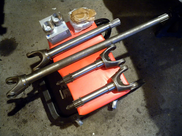
The new inner halfshafts arrived from Blanchard today, so it looks as if everything is now here. The two inner halfshafts looked in bad shape when unwrapped, the longer being encrusted in ancient dirt and the shorter having a thick coat of what appeared to be soft black paint or a protective layer of some sort. The paint was so thick in the splines that I thought they had been worn down. However, degreaser and a few passes of the brass wire wheel later, they came out looking like new, and the good Hardy Spicer shafts that they are.
I have now sourced an inexpensive press, which will make bearing and spacer installation much easier over the course of the restoration, and so will wait a few days to see how the press appears in reality before perhaps obtaining one and using that to put the halfshafts together.

I have now sourced an inexpensive press, which will make bearing and spacer installation much easier over the course of the restoration, and so will wait a few days to see how the press appears in reality before perhaps obtaining one and using that to put the halfshafts together.
Subscribe to:
Posts (Atom)